- 1 -
Desktop Hookup - Digital Submeter
The computer must have a standard, working com port (1-4) to use the software.
If there is any doubt, please verify Identifying COM Ports on your PC.
Newer PC's with USB but no com port can use adapters.USB Connections
The software installation (below pp 2-2.2) must be complete.
Software Installation - old PC with W98 or older
Software Installation - new PC with W98 or newer Shipments to first-time users are pre-configured with as much SETUP
information that was available when the order was made. The microMETER
arrives in the box with a temporary hookup so you can simply plug it in
and attempt a reading on your desktop. This should resolve most
common problems right away.
Step 1 - Connect the DB9 connector to a known, working PC comm port.
If this is not the case, determine what is available.
See Identifying COM Ports on your PC.
Step 2 - Connect power. The LED (under the terminal board) should flicker
in about 10 seconds and ever 10 seconds thereafter.
Another LED tester is included (with units shipped since 12/2/04).
See explanation in Troubleshooting - No Data.
Step 3 - Run the capture. You can do this different ways, depending on
your installation. It takes about 3 minutes to complete and it will
beep when done. If the wrong COM port is accessed, nothing will
happen and you may need to reboot the PC. If everything is OK, the
"Please wait" message should disappear after about 20 seconds. About
three minutes later it will say "Done" and beep at you. During the
capture, numbers will be "flash" behind the main panel.
with Cap2002.EXE: <-- Use this if you have W98 or better. Must use with XP,2000.
Choose the subdirectory
Choose the COM port
(This must be done twice the 1st time for Dis2002 to have before-and-after
readings to work with.) tutorial
With MICROM.EXE: <-- Use only if you have W95 or W3.x. Will work on W98.
File / Unit and Directory (default is C:\MICROMTR\MM01)
File / Capture tutorial
with MCAP.EXE or M2CAP.EXE (DOS):Downloads
Open DOS window and go to C:\MICROMTR\MM01
Type in MCAP 1 16 (enter, assuming COM 1 and the normal 16 readings) screen shot
Shipments to first-time users are pre-configured with as much SETUP
information that was available when the order was made. The microMETER
arrives in the box with a temporary hookup so you can simply plug it in
and attempt a reading on your desktop. This should resolve most
common problems right away.
Step 1 - Connect the DB9 connector to a known, working PC comm port.
If this is not the case, determine what is available.
See Identifying COM Ports on your PC.
Step 2 - Connect power. The LED (under the terminal board) should flicker
in about 10 seconds and ever 10 seconds thereafter.
Another LED tester is included (with units shipped since 12/2/04).
See explanation in Troubleshooting - No Data.
Step 3 - Run the capture. You can do this different ways, depending on
your installation. It takes about 3 minutes to complete and it will
beep when done. If the wrong COM port is accessed, nothing will
happen and you may need to reboot the PC. If everything is OK, the
"Please wait" message should disappear after about 20 seconds. About
three minutes later it will say "Done" and beep at you. During the
capture, numbers will be "flash" behind the main panel.
with Cap2002.EXE: <-- Use this if you have W98 or better. Must use with XP,2000.
Choose the subdirectory
Choose the COM port
(This must be done twice the 1st time for Dis2002 to have before-and-after
readings to work with.) tutorial
With MICROM.EXE: <-- Use only if you have W95 or W3.x. Will work on W98.
File / Unit and Directory (default is C:\MICROMTR\MM01)
File / Capture tutorial
with MCAP.EXE or M2CAP.EXE (DOS):Downloads
Open DOS window and go to C:\MICROMTR\MM01
Type in MCAP 1 16 (enter, assuming COM 1 and the normal 16 readings) screen shot
Step 4 - Display KWH. You can do this different ways, depending on
your installation. Program should not fail with an incomplete file.
If this happens, there was a problem in Step 3. You should see 0
amperes on channel 1 (or whatever you may have put through the
attached CT). You may see maximum amperes appear on other channels
you intend to use that do not have CT's connected yet.
with Dis2002.EXE: <-- Use this if you have W98 or better. Must use with XP,2000.
Choose the subdirectory
Choose the first and second captures (There must be at least 2.)
Click "mm.htm"
Click "ie browser" (or open a different browser and view mm.htm) tutorial
With MICROM.EXE: <-- Use only if you have W95 or W3.x. Will work on W98.
File / Unit and Directory (default is C:\MICROMTR\MM01)
Display / KWH tutorial
with DIS.EXE (DOS):Downloads
Open DOS window and go to C:\MICROMTR\MM01
Type in DIS (enter) screen shot
The first time you may see some residual values from calibration that
are not due to your usage. Click Reset/All to clear them out. Dis2002.EXE
does not use resets. Any pair of readings can be viewed.
We can also supply the software pre-installed to run from a USB memory stick.
- 2 -
See Vista for other methods for (Vista, Windows 7 - 10) pc's. The software, old and new, makes very little demand of a PC. Often a "junker"
can be dedicated to the job. For those wanting to utilize the "latest and greatest",
there are still some caveats:
1) 9/12/2007 - Be sure the pc's operating system supports serial communications. Some recent "home
versions" are omitting this support. Specify at the time of purchase that you need serial
capability and (preferably) get a built-in com port. The com port has 9 pins in 2 rows and is usually
found in the rear. See Identifying COM Ports on your PC.
2) 11/20/2007 - Avoid proprietary systems. If you are using a Compaq or HP box,
do not put anything in the root directory. Copy the cd folder "micromtr" to the desktop.
3) Avoid overloaded systems (10 lbs. in a 5 lb. bag). A corporate PC with
a time clock connection, security monitors, etc. had no usable com port
in spite of assurances that it did from the local support technician.
4) Avoid crippled systems. A corporate PC with standard o/s components
disabled or removed can be difficult to work with if direct access to files
and utilities is thwarted.
5) 02/25/2011 - from http://en.wikipedia.org/wiki/Serial_port#Settings
Many personal computer motherboards still have at least one serial port, even if accessible only through a pin
header. Small-form-factor systems and laptops may omit RS-232 connector ports to conserve space, but the
electronics are still there. RS-232 has been standard for so long that the circuits needed to control a serial
port became very cheap and often exist on a single chip, sometimes also with circuitry for a parallel port.
Any form of remote desktop access will, of course, make reports available from anywhere.
New browser-based software development is also reducing platform dependencies.
Reports and files are html/text-based to maximize compatibility.
Using the configuration CD:
Step 1 - Drag the CDROM folder micromtr to your pc desktop. Ignore anything else on the CD.
This should create a main folder called micromtr with subfolders mm01, etc.
This will contain your customized files per correspondence.
The "recovery" folder contains extra files only if they are needed.
Proceed to Step 3.
04/22/2008 - Using the email-attached, configuration zip file microzip:
Step 1 - Save the self-extracting file microzip.zip to your desktop.
Step 2 - Doubleclick into it and extract all files.
Note: This will put the folder "micromtr" inside a desktop folder called "microzip".
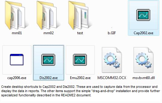
Finish the installation:
Step 3 - If desired, create desktop shortcuts to run micromtr\Cap2002.EXE and
micromtr\Dis2002.EXE.
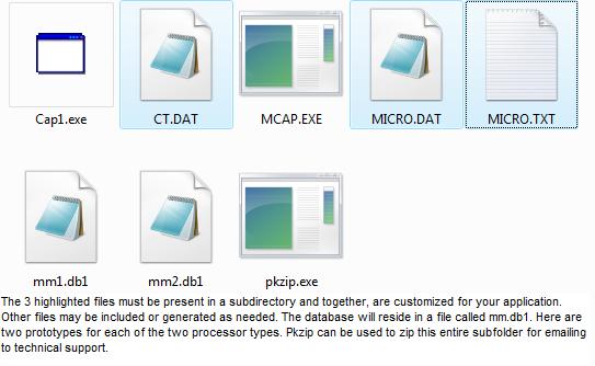
Step 4 - Verify the following micromtr directory structures before proceeding.
micromtr
Cap2002 EXE - The capture program that reads the com port and builds the database.
Dis2002 EXE - The display program that reads the database and creates the reports.
b gif - a graphic pixel used by Dis2002.EXE
mscomm32.ocx - MS runtime file - If placed here, there is no need to disturb anything else on your pc.
msvbvm60.dll - MS runtime file - If placed here, there is no need to disturb anything else on your pc.
mm01 (directory) - You may have as many more as needed, mm02, etc. Customized
folders may have different names, usually 4 characters long based on your request. May appear as mm01, etc.
TEST (directory) - simply to run captures or test other items without affecting anything else.
micromtr\mm01
CT DAT 1,168 05-28-96 12:46p CT.DAT
MICRO TXT 438 01-15-96 5:46p MICRO.TXT
MICRO DAT 175 02-01-96 9:34p MICRO.DAT
Several data files for one mM can be on \micromtr\mm01 but only these three are needed
to start the new software. There should be no subdirectories under this one.
Any additional subdirectories (folders) nested under \micromtr\mm01 will cause
Dis2002.EXE to fail with a "problem with MM.DB1 file" message.
A few new filenames will be created later when programs are used. MM.DB1 is the main database.
The software, old and new, makes very little demand of a PC. Often a "junker"
can be dedicated to the job. For those wanting to utilize the "latest and greatest",
there are still some caveats:
1) 9/12/2007 - Be sure the pc's operating system supports serial communications. Some recent "home
versions" are omitting this support. Specify at the time of purchase that you need serial
capability and (preferably) get a built-in com port. The com port has 9 pins in 2 rows and is usually
found in the rear. See Identifying COM Ports on your PC.
2) 11/20/2007 - Avoid proprietary systems. If you are using a Compaq or HP box,
do not put anything in the root directory. Copy the cd folder "micromtr" to the desktop.
3) Avoid overloaded systems (10 lbs. in a 5 lb. bag). A corporate PC with
a time clock connection, security monitors, etc. had no usable com port
in spite of assurances that it did from the local support technician.
4) Avoid crippled systems. A corporate PC with standard o/s components
disabled or removed can be difficult to work with if direct access to files
and utilities is thwarted.
5) 02/25/2011 - from http://en.wikipedia.org/wiki/Serial_port#Settings
Many personal computer motherboards still have at least one serial port, even if accessible only through a pin
header. Small-form-factor systems and laptops may omit RS-232 connector ports to conserve space, but the
electronics are still there. RS-232 has been standard for so long that the circuits needed to control a serial
port became very cheap and often exist on a single chip, sometimes also with circuitry for a parallel port.
Any form of remote desktop access will, of course, make reports available from anywhere.
New browser-based software development is also reducing platform dependencies.
Reports and files are html/text-based to maximize compatibility.
Using the configuration CD:
Step 1 - Drag the CDROM folder micromtr to your pc desktop. Ignore anything else on the CD.
This should create a main folder called micromtr with subfolders mm01, etc.
This will contain your customized files per correspondence.
The "recovery" folder contains extra files only if they are needed.
Proceed to Step 3.
04/22/2008 - Using the email-attached, configuration zip file microzip:
Step 1 - Save the self-extracting file microzip.zip to your desktop.
Step 2 - Doubleclick into it and extract all files.
Note: This will put the folder "micromtr" inside a desktop folder called "microzip".
Finish the installation:
Step 3 - If desired, create desktop shortcuts to run micromtr\Cap2002.EXE and
micromtr\Dis2002.EXE.
Step 4 - Verify the following micromtr directory structures before proceeding.
micromtr
Cap2002 EXE - The capture program that reads the com port and builds the database.
Dis2002 EXE - The display program that reads the database and creates the reports.
b gif - a graphic pixel used by Dis2002.EXE
mscomm32.ocx - MS runtime file - If placed here, there is no need to disturb anything else on your pc.
msvbvm60.dll - MS runtime file - If placed here, there is no need to disturb anything else on your pc.
mm01 (directory) - You may have as many more as needed, mm02, etc. Customized
folders may have different names, usually 4 characters long based on your request. May appear as mm01, etc.
TEST (directory) - simply to run captures or test other items without affecting anything else.
micromtr\mm01
CT DAT 1,168 05-28-96 12:46p CT.DAT
MICRO TXT 438 01-15-96 5:46p MICRO.TXT
MICRO DAT 175 02-01-96 9:34p MICRO.DAT
Several data files for one mM can be on \micromtr\mm01 but only these three are needed
to start the new software. There should be no subdirectories under this one.
Any additional subdirectories (folders) nested under \micromtr\mm01 will cause
Dis2002.EXE to fail with a "problem with MM.DB1 file" message.
A few new filenames will be created later when programs are used. MM.DB1 is the main database.
 Check Type 1 (discontinued) or Type 2 at the bottom of the form (v1.18).
Software Installation - older PC with W98 and older tutorial
The Windows program MICROM.EXE can utilize COM 1,2,3 or 4 using Win 98 or older.
Please see the DOS Archive for earlier program notes.
Note 11/13/04 - The floppy is no longer supplied. Instead, a folder on the CD
called "floppy" will contain the customized files and the INSTALL.BAT file.
Transfer this to a floppy disk.
1/5/06 - Windows does not recognize my file suffixes .dat and .db1 as text files.
Right-click open and "choose program from a list" (notepad)
Check the box below to always open with notepad.
It is assumed that the PC has a hard drive called C: with no directory
called MICROMTR and a floppy drive called A:
Step 1 - Place the diskette in A: and execute INSTALL.BAT from A:
Step 2 - Verify the following result before proceeding.
If the files wound up elsewhere,
manually copy them to these directories:
About 5 files should be on C:\MICROMTR. They are:
MICROM EXE 62,489 03-31-98 12:29a MICROM.EXE
VBRUN300 DLL 398,416 09-14-96 3:09p VBRUN300.DLL
VBCOMM VBX 9,296 08-22-92 10:00p VBCOMM.VBX
README2 TXT 05-08-01 6:23p readme2.txt (redirected to website)
README TXT 05-08-01 6:23p readme.txt (redirected to website)
MM01 (directory) You may create as many more as needed, MM02, etc.
About 11-12 files should be on C:\MICROMTR\MM01 (data files for one mM).
There should be no subdirectories under this one.
CT DAT 1,168 05-28-96 12:46p CT.DAT
MICRO TXT 438 01-15-96 5:46p MICRO.TXT
MCAP EXE 45,734 07-22-96 11:28a MCAP.EXE
MICRO DAT 175 02-01-96 9:34p MICRO.DAT
XX CAP 292 12-19-96 10:15a XX.CAP
CT DTE 336 05-04-95 6:57p CT.DTE
MICRO2 CAP 336 12-19-96 10:16a MICRO2.CAP
MM BAT 320 03-08-99 12:59p MM.BAT
CT RES 279 05-04-95 6:57p CT.RES
MICRO PRT 1,632 12-31-99 6:41p MICRO.PRT
CT CAP 279 01-10-99 12:36p ct.cap
DIS EXE <-- add this file from download if needed for DOS display
Step 3 - Create a desktop shortcut to run C:\MICROMTR\MICROM.EXE.
Check Type 1 (discontinued) or Type 2 at the bottom of the form (v1.18).
Software Installation - older PC with W98 and older tutorial
The Windows program MICROM.EXE can utilize COM 1,2,3 or 4 using Win 98 or older.
Please see the DOS Archive for earlier program notes.
Note 11/13/04 - The floppy is no longer supplied. Instead, a folder on the CD
called "floppy" will contain the customized files and the INSTALL.BAT file.
Transfer this to a floppy disk.
1/5/06 - Windows does not recognize my file suffixes .dat and .db1 as text files.
Right-click open and "choose program from a list" (notepad)
Check the box below to always open with notepad.
It is assumed that the PC has a hard drive called C: with no directory
called MICROMTR and a floppy drive called A:
Step 1 - Place the diskette in A: and execute INSTALL.BAT from A:
Step 2 - Verify the following result before proceeding.
If the files wound up elsewhere,
manually copy them to these directories:
About 5 files should be on C:\MICROMTR. They are:
MICROM EXE 62,489 03-31-98 12:29a MICROM.EXE
VBRUN300 DLL 398,416 09-14-96 3:09p VBRUN300.DLL
VBCOMM VBX 9,296 08-22-92 10:00p VBCOMM.VBX
README2 TXT 05-08-01 6:23p readme2.txt (redirected to website)
README TXT 05-08-01 6:23p readme.txt (redirected to website)
MM01 (directory) You may create as many more as needed, MM02, etc.
About 11-12 files should be on C:\MICROMTR\MM01 (data files for one mM).
There should be no subdirectories under this one.
CT DAT 1,168 05-28-96 12:46p CT.DAT
MICRO TXT 438 01-15-96 5:46p MICRO.TXT
MCAP EXE 45,734 07-22-96 11:28a MCAP.EXE
MICRO DAT 175 02-01-96 9:34p MICRO.DAT
XX CAP 292 12-19-96 10:15a XX.CAP
CT DTE 336 05-04-95 6:57p CT.DTE
MICRO2 CAP 336 12-19-96 10:16a MICRO2.CAP
MM BAT 320 03-08-99 12:59p MM.BAT
CT RES 279 05-04-95 6:57p CT.RES
MICRO PRT 1,632 12-31-99 6:41p MICRO.PRT
CT CAP 279 01-10-99 12:36p ct.cap
DIS EXE <-- add this file from download if needed for DOS display
Step 3 - Create a desktop shortcut to run C:\MICROMTR\MICROM.EXE.
- 3 -
DOS Program Summary
Billing Suite:
Input files Executable program Output files
COM port CAP.EXE (obsolete) CT.CAP, MICRO2.CAP
MCAP.EXE (modem supt)
3CAP.EXE (3-phase)
MONITOR.EXE (alarm)
MMICAPPG.EXE (COM 3,4)
TCAP.EXE
CT.DAT, MICRO.DAT SETUP.EXE CT.DAT, MICRO.DAT
CT.CAP, MICRO2.CAP DIS.EXE MICRO.PRT
CT.RES, CT.DTE
CT.DAT, MICRO.DAT
MICRO.TXT (1st line)
CT.CAP, MICRO2.CAP RESET.EXE CT.BIL, CT.BI2
CT.RES, CT.DTE CT.RES, CT.DTE
CT.DAT, MICRO.DAT
Advanced Billing:
Input files Executable program Output files
CT.BIL, CT.AFF MAP.EXE CUS.BIL
Produces CUS.BIL from concatenated
CT.BIL('s) to consolidate as directed
in CT.AFF. Copy back to CT.BIL
CT.BIL, MICRO.TXT PRTBILL.EXE BILLS.OUT
Produces formatted bills,
4 to a page in an ASCII file
CT.BIL SUMM.EXE CT.SUM
Adds one or multiple CT.BIL and
reconciles total to statement.
Analytical Suite:
Input files Executable program Output files
USAGE.CAP USAG4.EXE USAGE.Pxx
Produces USAGE.Pxx (17 24-hour
files from USAGE.CAP (8640 CT.CAP))
USAGE.Pxx PLOT4.EXE Screen VGA plot of amp,KW over time
USAGE.Pxx DEMAND.EXE DEMAND.OUT
Produces 15, 30 or 60 minute
interval data for all CT's
DEMAND.OUT DSPLIT.EXE DSPLIT.OUT
Produces plot data for 1 CT
or system total (CT 17).
DSPLIT.OUT PLOT4.EXE Screen VGA plot of amp,KW over time
CT.CAP, MICRO2.CAP DISPF.EXE Screen
CT.RES, CT.DTE Produces power factor display
CT.DAT, MICRO.DAT for paired channels using powerstats kit.
MICRO.TXT (1st line) Run in DOS with redirected output to create print file.
Utility Suite:
Input files Executable program Output files
SEP.INP SEP.EXE SEP.OUT
Partition larger files into smaller ones.
CT.BIL COMMA.EXE COMMA.OUT
Comma delimit CT.BIL for spreadsheet import.
CT.BIL IDEAL.EXE IDEAL.OUT
Produce IDEAL(tm) extract.
any SHOW.EXE screen
Use to examine the README files on your screen.
any PRTDOC.EXE printer
Use to print the README files by page number.
Note: These are all archived in the download page.
download
- 4 -
DOS Program Detailed Descriptions
*** USAG4.EXE
USAG4.EXE produces time-axis graphs of power usage over a 24
hour period. Run the CAPture program with 8640 readings.
This will require 24 hours to complete. At completion,
CAPture will start the DISplay program. Exit the DISplay
program and rename the CT.CAP file to USAGE.CAP. Rename
MICRO2.CAP to USAGE.DTE.
Run USAG4 (without any parameters or prompts). It will
produce 17 files of the form USAGE.Pxx where xx is 01 thru
17. Then run PLOT4. A series of 17 VGA plots will appear.
The files called USAGE.Pxx have 540 records (8640/16) for
each CT and the system total. They can be imported to a
spreadsheet. Records contain ampere data.
*** DEMAND.EXE, DSPLIT.EXE, PLOT4.EXE:
DEMAND.EXE and DSPLIT.EXE can be used to collect demand data
in 15, 30 and 60 minute intervals. DEMAND.EXE reads a copy of
CT.CAP that is renamed to USAGE.CAP and puts out a file
called DEMAND.OUT. This file has the CT# and max kw for 30
minute intervals in 816 records (which represents 17 sets of
48). CT 17 is the system total. DSPLIT.EXE filters
DEMAND.OUT into DSPLIT.OUT for a specific CT and drops the
CT# to save disk space, resulting in 48 records. Follow with
PLOT4.EXE.
*** MONITOR.EXE:
MONITOR.EXE can be run instead of CAP.EXE to capture only
those readings exceeding high or low limits entered by the
user. It runs until stopped manually and stores exception
data in CT.CAP and corresponding time and date in MICRO2.CAP.
It can give an alarm when exceptions occur. High and low
limits are in raw scale form (0-255) which must be
interpreted for the corresponding CT size.
*** MMICAPPG.EXE
Lockheed Martin substitute for CAP.EXE with COM3 and COM4
operational.
*** MCAP.EXE
Functionally equivalent to CAP.EXE but combines modem control
and multiple microMETER select (see SWITCH below). This runs
from a batch file and has no prompts. See examples in MM.BAT
*** PRTBILL.EXE (PRTBILL 22)
Produces BILLS.OUT text file from CT.BIL and MICRO.TXT
Add parameter 22 to put 22 blank lines after each set of 4
bills. Vary this to make DOS PRINT print your bills four-to-
a-page on your printer.
- 4.5 -
DOS/Windows Instructions for capture thru mouse port
This was a very common scenario. An older PC has a mouse and modem tying up
COM1 and COM2. Usually the mouse is on COM1 and attaches with a 9-pin
female D connector in the back. Install this .BAT file and use the
following instructions:
Put MM.BAT in the C:\windows directory and install DIS.EXE in the
C:|MICROMTR\MM01 directory
echo off
cd\MICROMTR\MM01
mcap 1 00016 0...............
dis rem (if desired for immediate DOS display)
cls
echo Reconnect mouse and disconnect mM at pole to protect from lightning.
echo Type exit (enter)
echo Click up mM icon to view, reset all and print bills.
pause
microMETER Instructions
1) Restart in DOS mode (not the Windows DOS prompt)
2) MM (enter)
connect MM at PC and pole (phone jack)
(Capture will take 3 minutes - press enter)
Print screen now, if desired - use print screen key at upper right)
0 to exit DOS display
3) Connect mouse, diconnect mM at pole (phone jack) - press enter
4) Type EXIT, press enter
5) Double click mM icon
6) Display, KWH
7) Reset, All
8) Reset, Print Bills (if desired)
9) Close
To further ID circuits:
Repeat 2) looking for AMPS = 0
Another, very simplified method for reading more than one processor:
simple batfiles for mm
1.bat - put this where DOS "lands"
cd\micromtr\mm01
mcap 1,16
dis enter 0 to exit
reset 17
cd\micromtr\mm02
2.bat - put this in mm02
mcap 1,16
dis enter 0 to exit
reset 17
exit
procedure:
Connect at both poles.
Attach plug 1 to pc.
click up DOS and enter the following:
1
0
change to plug 2 and enter the following:
2
0
click up reports (on desktop) and print.
Disconnect at poles.
- 10 -
DOS/Windows Data Files
All these files can be accessed with a plain text editor.
Use this Handy-Dandy Ruler for checking field lengths and starting positions:
....+....1....+....2....+....3....+....4....+....5....+....6....+....7....+....8
0 0 0 0 0 0 0 0
Files 1-3 are used universally by all s/w. They represent your configuration.
1. MICRO.DAT
12.75 (This is fixed for v1.04 microMETER hardware)
2390.625 (286875 / your avg line voltage if using RMS)
6.96 (cents / kwh)
1=color/0=mono (used for default COM Port in Windows Program)
3 rows of 4 numbers - special meanings for various programs
example:
12.75
2515.632
8.5
1
0 1 2 3
4 5 6 7
7 7 0 0
Line 5 1st number: 0=non-analytic mMI or mMII - alternating row color in Dis2002.EXE
Line 5 1st number: 2=analytic mMI - paired row color in Dis2002.EXE and special pf calc
Line 5 1st number: 3=3-phase mMII - triple row color in Dis2002.EXE
Line 5 2nd number: 0=unselect true power in Dis2002 display (v1.15)
2. MICRO.TXT
Company name (1st line) and text for DISplay and PRTBILL (7 lines total)
microMETER Corp.
Energy usage charges due and payable for the period ending.
Taxes and customer charges have been added proportionately.
Thank you for your prompt payment.
Customer Billing Period Usage Amount Due
Rate: Non-demand, Non-TOU - Customer chg incl. @ xxxx cts/kwh
3. CT.DAT
CT #1 descr, CT size, power factor, circuit voltage, low alarm limit, high alarm limit
CT #2 descr, CT size, power factor, circuit voltage, low alarm limit, high alarm limit
...
Use this Handy-Dandy Ruler for checking field lengths and starting positions:
....+....1....+....2....+....3....+....4....+....5....+....6....+....7....+....8
0 0 0 0 0 0 0 0
example: period is used to reserve space
1 - Range "0040,1.00,240,000,999 .
2 - Kitchen "0020,1.00,120,000,999 .
3 - Water Heater "0020,1.00,240,000,999 .
4 - Refrigerator "0020,1.00,120,000,999 .
5 - Pumphouse "0020,1.00,120,000,999 .
6 - Pool "0020,1.00,240,000,999 .
7 - Well Pump "0020,1.00,120,000,999 .
8 - Air Handler "0020,1.00,240,000,999 .
9 - Laundry Room "0020,1.00,120,000,999 .
10 - Living Room, Attic "0020,1.00,120,000,999 .
11 - Small Bedrooms "0020,1.00,120,000,999 .
12 - Dryer "0020,1.00,240,000,999 .
13 - A/C "0020,1.00,240,000,999 .
14 - Garage "0020,1.00,120,000,999 .
15 - "0000,1.00,120,000,999 .
16 - "0000,1.00,120,000,999 .
The low,high alarm limits ------------> 000,999 are passive until changed. Setting the
low limit above 000 or setting the high limit below 254 will trigger alarm related events
in any programs that use them. They are compared to the raw pulse count (second number from mM).
Use this Handy-Dandy Ruler for checking field lengths and starting positions:
....+....1....+....2....+....3....+....4....+....5....+....6....+....7....+....8
0 0 0 0 0 0 0 0
----------------- legacy files used by MICROM.EXE and DOS programs ------------------------
Files 4-7 represent any given time span in the legacy s/w.
4. CT.CAP
CT#, current analog, kwh low bucket, kwh high bucket
...
example:
16,000,65391,00001 Note: It starts wherever the mM happens to be.
01,238,48529,00048
02,012,45922,00153
03,000,42821,00236
04,023,32445,00457
05,003,07966,00035
06,000,22206,00236
07,000,27452,00003
08,014,44283,00159
09,015,62512,00128
10,000,62684,00052
11,016,39015,00096
12,000,43977,00067
13,166,63162,00594
14,003,10802,00127
15,000,65385,00009
5. CT.RES
copy of CT.CAP data at last reset (to be subtracted from next CT.CAP)
6. MICRO2.CAP
time, date corresponding to CT.CAP
example:
19:43:48 07-17-2003
19:43:57 07-17-2003
19:44:07 07-17-2003
19:44:17 07-17-2003
19:44:27 07-17-2003
19:44:37 07-17-2003
19:44:47 07-17-2003
19:44:57 07-17-2003
19:45:07 07-17-2003
19:45:17 07-17-2003
19:45:27 07-17-2003
19:45:37 07-17-2003
19:45:47 07-17-2003
19:45:57 07-17-2003
19:46:07 07-17-2003
19:46:17 07-17-2003
7. CT.DTE
copy of MICRO2.CAP data at last reset
8. CT.BIL (CT.BI2 has same data appended to old and never cleared)
CT descr, kwh, $, from reset date, to date of billing
4 - Refrigerator 10-16-1995 to 01-08-1996 252 kwh $ 21.41
....+....1....+....2....+....3....+....4....+....5....+....6....+....7....+....8
0 0 0 0 0 0 0 0
9. MICRO.PRT
screen displays from DIS.EXE for emailing, remote printing, etc.
- 11 -
Windows Program MICROM.EXE MICROM.EXE screen shot
A Windows gui program is available to replace all of the DOS
programs and provide a more user friendly interface.
It is designed to operate from a directory called
C:\MICROMTR and support several mM's installed in subdirectories
called MM01, MM02, etc.
The subdirectories require the CT.xxx
and MICROx.xxx files that are specific to each unit. The
executables reside in one place under C:\MICROMTR. For DOS
compatibility, the DOS executables must be copied into each
of the subdirectories. The Windows program uses some MICRO.DAT
parameters for different purposes and may affect the color
display in DIS.EXE. The executable is MICROM.EXE and requires
VBRUN300.DLL and VBCOMM.VBX to be present.
download
Using Windows "RUN" or "FIND" features, locate the MICROM.EXE
program in C:\MICROMTR. Right click the MICROM.EXE. A shortcut
will appear. Drag the shortcut to the desktop.
The functions of the DOS programs were implemented in
dropdown menus. Some dropdowns toggle a setting that affects
another dropdown. For example, ALTERNATE will do nothing when
clicked but the next time KWH is clicked, the alternate
display will appear. Resetting certain CT's (not all)
requires a little tag (lowercase r) to be placed in the
textboxes. Clicking SELECTIVE (under RESET) will reset only
those CT's so marked. If you understand the DOS functions,
the Windows version will be easy to adapt to. If you are new
to the microMETER software, the Windows version should be
easier to learn. We welcome suggestions and make changes to
improve our system for our clients.
download
MICROM.EXE Dropdown menus:
FILE ********
Unit and Directory - Use to set the correct data directory for a
particular mM. Also use to select the desired mM unit via an
optional switch. The hex codes 0-F correspond to MM01-mm16. A
COM port override selects COM1-4. A modem can be dialed with a
number entered on this panel.
Dial - Establishes remote connection by dialing the number entered
above. Watch external modem to see carrier detect before
proceeding with CAPTURE
Capture - initiates capture of 16 readings through the selected COM
port. Watch for "done" message when complete. Follow with HANGUP if
using a modem.
24-Hour - Same as CAPTURE but 8640 readings are captured into USAGE
files. THIS WILL NOT UPDATE THE DISPLAY. This process completes
in 24 hours and may be minimized to allow other PC activity.
Hangup - Hang up modem following a remote capture (or 24 hour).
Exit - Return to Windows.
DISPLAY ********
KWH - Click to display captured data (following CAPTURE)
Alternate - Click to toggle display mode to KW, then click KWH
Reconcile to - After placing the kwh from your utility bill in
the bottom kwh box, click to force data to add up to this
new value. Click DISPLAY again to see the result.
Temperatures - If thermistors are used to collect temperature data
on unused kwh channels, the results will be displayed separately
from the kwh data. Alternate toggle selects degrees C.
SETUP ********
CT - Enter CT descriptive data on this panel.
microMETER - Use to enter global data for all the mM channels.
RESET ********
Selective - Click to reset any channel(s) with a lowercase "r" entered
at the leftmost position of the circuit name box.
All - Click to generate billing data and clear the kwh readings.
Print Bills - Click (after a RESET) to print the billing data.
Unreset - Restores ALL kwh accrued since the mM was installed.
This is NOT used in normal monthly billing procedures.
ABOUT ******** Displays "ABOUT" information
HELP ********
Readme - Displays the README.TXT file
Readme2 - Displays the README2.TXT file
24 HOUR DEMAND ********
Process New Data - After a 24 hour capture has been completed, click
this entry to process the data. It takes about 15 minutes and only
needs to be done once. Any previous demand data graphics will be
lost. If desired, save the USAGE.Pxx, DEMxx.Pxx files first.
View - Access any of the processed data. Note that interval demand
data will not be available until processed by the PROCESS DEMAND
entry at the end of this menu.
Instantaneous Select - After viewing any interval data, click to make
View show the instantaneous graphs again.
15 Minute Select - Changes View pointer to 15 minute graphs
30 Minute Select - Changes View pointer to 30 minute graphs
60 Minute Select - Changes View pointer to 60 minute graphs
Process Demand - Click to further process the 24 hour data prior
to viewing any intervals (15, 30, 60). This takes a few minutes
and is only run once for new data.
download
Software Functionality
- 13 -
Software Functionality
This metering software renders an itemized bill by individual
circuit breaker. A call (via modem or direct) is initiated to
the microMETER (tm) from the PC. The microMETER's (tm)
program responds with a stream of data containing circuit
identification, instantaneous demand and integrated power for
each of 16 circuits.
The screen fills with five columns containing the circuit
number, custom description, amperes, kilowatt hours and
dollar cost. The screen is date and time stamped. A setup
option permits the user to update the custom descriptions,
CT calibration factors for amperage and energy costs.
Other options allow reset (and unreset) of kwh column values.
The unreset display shows the monotonic increasing values
coming from the microMETER (tm). Like an odometer, they may
eventually wrap in 85 or so years, but that can be easily
accommodated by the user's descendants. Continuous logging is
also available. Dual monitoring using RMS and true power
setups can uncover power factor problems that can be wasting
energy dollars if left uncorrected.
- 14 -
Identifying COM ports on your PC.
The Windows program Cap2002.EXE can utilize COM 1,2,3 or 4.
The Windows program MICROM.EXE can utilize COM 1,2,3 or 4.
The DOS program MCAP.EXE can only utilize COM 1 or 2 (with modem support).
The DOS program 3CAP.EXE can only utilize COM 1 or 2 (for three-phase).
The DOS program MMICAPPG.EXE (provided by Lockheed Martin) can access
COM 1 thru 4 but does not have modem support.
Each PC is different, sad to say. A DOS PC (without a mouse)
usually has COM 1 or 2 available in the back. The connector
will always be male (pins sticking out) and may have 9 or 25
pins in two rows. Do not try to use a printer port (25 holes
instead of pins).
A PC with an internal modem will tie up one of the COM ports.
A PC with a mouse will (likely) tie up one of the COM ports.
A PC cannot use COM 1 and COM3 together because they share
IRQ4. A PC cannot use COM 2 and COM 4 together because they
share IRQ3. If the PC has a mouse and a modem, and is
properly configured, the mouse is on COM 1 and the modem on
COM 2. If your PC has both, you can use the mouse port by
exiting Windows and running one of the DOS programs for the
duration of the Capture. (Unplug the mouse and connect the
mM until 16 readings have been made.) You may then view the
results with the Windows program or use DIS.EXE (DOS),
available as a download.
Invoke a terminal emulator program such as PROCOMM or Windows
HyperTerminal. Set the parameters to 300 Baud, 8 bits, no
parity and attempt to read the microMETER output directly. It
will appear as a stream of 4 numbers (separated by commas)
every ten seconds. These values must be interpreted by the mM
software to yield correct KWH data.
- 15 -
Combining Time Intervals
Conceptually, the CT.CAP and MICRO2.CAP files hold the latest
"meter readings" and the corresponding time stamps. The
CT.RES and CT.DTE files are copies of this data made at the
time of the last RESET. This is like the "meter readings taken
last month". Both DISplay and RESET use the differences of these
files to produce the new KWH consumption and the time period involved.
If two complete sets of data were created for different time intervals,
a single time interval can be easily created. For example, you have a
complete set of files for April and another set for June.
The April data had a CAPture followed by RESET done on the 1st.
The June data had a CAPture done on the 31st. If you take the CT.RES and
CT.DTE files from April and the CT.CAP and MICRO2.CAP files from
June and put them in the same directory, the resulting DISplay will
show KWH that accrued from April 1 to June 30.
The new CAP2002.EXE program saves every capture in MM.DB1. This file will
allow new programs to reconstruct any billing time period easily and create
graphs and statistics without relying on continous demand capture. It also
generates the legacy .CAP files for full backward compatibility.
- 32 -
mMI prior to 1996
*** ANSI tests:
ANSI C12.1 testing of three microMETER units at Lockheed
Martin has demonstrated accuracy to be +/- 2.3% over all
conditions.
The tests also indicate that the system is suitable for 50 Hz
installations.
*** Larger CT capacity or clamp-ons:
CT's may be purchased from other suppliers that convert say,
1000 amperes to 5. Any CT that produces a 5 ampere metering
current can be read by a CT20 with four passes quite
accurately. Example, you use a 500:5 commercial CT as a
"front-end". Take one of its leads and make 4 passes through
a CT20 and short it to the other lead (see illustration).
When 500 amperes flows through the window of the big CT, 5
amperes will flow in the secondary, appearing as 20 amperes
to the CT20. Enter 500 in the software SETUP since this is
the effective CT size. A small phase shift will be added by
the extra CT but should be negligible for most submetering
applications using true power. Compensation can be applied on
special request. There is no effect on apparent power.
CT20 _ 500:5
| |
H2||H1 put X1 in at H1 H2|_|H1
X1 - ----|| <-------------------< X1 ---|
X2 + ----| X2 ---|
12/30/99
A custom switch, not based on a mM board is available that can
switch a few mM's automatically - cost is about $50 per mM.
*** Scale 2 pre-set:
Software distributions may contain a value of 2516.447
instead of the theoretical 2390.625. This was to provide
better "out-of the box" kvah accuracy prior to
reconciliation. It assumes an overall power factor of .95.
*** Special Hardware Applications - 10/17/95
Time-of-Use can be implemented two ways. Dual mM's recording
night and day with the same CT's or a modified mM with a
variable sensitivity. The latter works but deals strictly
with cost units rather than pure KWH. Power factor analysis
(with correlated data) can be done with dual mM's reading the
same CT's. Set one in true power mode, the other in apparent
power mode.
- 33 -
Network True Power (mMI)
Uses standard CT's (no PCCT's)
For each 24 apartments, 48 channels will be assigned as
follows:
Apt# mM phase A mM phase B mM phase C
1 1 1
2 2 2
3 3 3
4 4 4
5 5 5
6 6 6
7 7 7
8 8 8
9 9 9
10 10 10
11 11 11
12 12 12
13 13 13
14 14 14
15 15 15
16 16 16
17 17 17
18 18 18
19 19 19
20 20 20
21 21 21
22 22 22
23 23 23
24 24 24
The MAP.EXE program and CT.AFF are used to create CT.BIL
for 24 apartments. SUMM.EXE can be used to reconcile for all
apartments.
The above is the "government" way to submeter open-wye. A cheaper
way to do it follows:
Domestic open-wye (120/208) circuits can be treated as 1 phase
for percentage billing purposes if both wires can fit through
the 1/2" CT opening. Demand accuracy in this case is +/- 8% but
it evens out quite well for each tenant's total monthly usage.
- 34 -
Installation for a 3-phase mMI array (deprecated - use mMII)
CAUTION: Commercial (3rd party) CT's produce hazardous
secondary voltages. These leads must be shorted together when
operating. Our CT's are as safe as a flashlight.
Description:
The A-phase J-box is on the left and is connected to B-phase
J-box via 3/4" PVC tee, opening downward. The C-phase unit,
on the right, is directly connected to the B-phase unit in
the center. Three 9-pin computer connections exit on the right.
The shortest runs all the way back to the A-phase unit on the left
(and so on).
The PT connections are to be made to the 6-terminal barrier
strip. The microMETER CT connections are made to the internal
terminal boards. The first has been done as an example. The
CAT 3 enters the tee and splits left and right. The C-phase
pairs (blue and blue white) tunnel over to the far right J-
box. Locate the array centrally to the anticipated CT
placements. Unroll the attached CAT 3 cable and cut at the
desired length to reach the first load.
Mount the three PT's (24-volt control transformers) together
where they can be controlled by a 3-phase circuit breaker.
Identify the 3 primary common wires and connect them
together. If there is a neutral at ground potential, include
it in this connection. Connect the appropriate primary leads
to the A, B and C phases. For a 480-volt delta or wye, the
primary voltages should be 277 volts, since the primaries
will be connected as a wye. The 24-volt secondaries will have
color-coded leads or terminals but may not be marked for
phasing purposes. Connect each secondary in a consistent
manner to the color-coded pairs of a length of CAT 3 cable
long enough to reach the six-terminal barrier strip (on the
mM array). Use the following rule:
A-phase orange and orange-white
B-phase green and green-white
C-phase blue and blue-white
Tie off the brown pair.
At the array, connect the orange-white to the 1st terminal
(marked). Connect the green-white to the second. Connect the
blue-white to the third. Do not connect the others yet. Apply
power and verify that voltages between any two unconnected
secondary wires is approximately 50 volts ac and that voltage
between any unconnected secondary wire and the connected wire
is approximately 29 volts. (This is normal for unloaded
secondaries).
Turn off the breaker and connect the orange, green and blue
wires to the 4th, 5th and 6th terminals, respectively. This
can be done later if you need the breaker on for other
reasons. Tie off the brown pair.
The CT connections at the first load can be made in
accordance with the hookups described in README2. DO NOT
connect any CT type other than the microMETER CT's to the
CAT 3 cable or the microMETER units. Use the same color
coding (above, for PT's) and install them the same way. In
the end, if the phasing is incorrect, all we need do is flip
the PT connections (no big deal). A good rule to follow is:
H1 faces the source of power (usually the breaker). H1 and H2
are marked on each side of most commercial CT's. The 5-ampere
secondaries are marked X1 and X2. The X1 is always the same
phase as H1, so treat it as the "source" for a microMETER CT.
The H1 side of a microMETER CT is the side without the wire.
You put the X1 lead in thru the H1 side. This keeps the
phasing consistent. MicroMETER CT's have two leads of the
same color but different lengths (DO NOT TRIM EVEN!). The
long one is the "X1" or "+" to the mM processor. The idea
behind using microMETER CT's to read commercial CT'
secondaries is to gain the ability to use thin Class 2 wiring
for unlimited runs and to scale the range properly. Scaling
means to "max out" the microMETER CT with enough passes of
the big CT's secondary when it "maxes out". The software is
given the real capacity of the big CT, rather than the size
of the microMETER CT so the readings are correct. Usually 4
passes are made with a 5-amp secondary thru a CT20.
Sometimes, to improve resolution at the normal operating
currents, additional passes are made and/or a different mM CT
is used. The software must always be loaded with this "max
out" value.
- 36 -
Powerstats Kit (mMI only)
The Powerstats Kit is a means of toggling back and forth between
apparent power and true power for the purpose of deriving power
factor data, KVAR, etc. It is a solid-sate relay* that replaces the
selection jumper. It can be controlled a number of ways, by a PC, a
manual switch, or the mM itself. By grounding the white lead, the mM
changes from true power mode to kvah mode. By tying this wire
to the LSB contolling the MUX, even-numbered channels read true power
and odd channels read apparent. By hooking CT's to paired channels
we get an eight-channel analytical meter. This is done by stripping
1.5" from the "+" lead and folding back 1". Bend the folded part back
with an eighth inch radius to form a bifurcated "plug" to enter
adjacent terminals. Pair the odds and evens of the + connections this
way. For the - connections (which are common and connected together),
this bifurcation is not necessary. If using #24 wire, strip 1" and
fold back half for a better grip and wire only the odds (or evens).
Note: Terminal Board C is marked incorrectly. The + side is closest to
the ribbon. DO NOT OVER TIGHTEN THE SCREWS. If you damage a trace on
the Terminal Board, you can pick up the connection again at the
corresponding pin that rises from the center.
* This exotic little part (from Lockheed) has been cleverly replaced with
the following (some time in 2003):
A 2N2907 pnp transistor is installed with the emitter connected to the
rms (ap) selector pin. The collector is connected to the center pin
(a/d input) and the tp pin. The base is connected via a 1 meg resistor
to the MUX lsb. When the lsb is low (for the odd channels), the ap output,
which is always > or = 0, will turn it on. This makes the a/d input follow
low Z signal from the rms ap measurement. When the lsb is high, the
transistor is off (not there) and the a/d input follows the high Z signal
from the multiplier (tp) measurement which we shorted together. This works
well as long as two conditions are met. The rms signal of interest
is above the .6 volt threshold to bias the transistor. And, any unused
CT connections are jumpered to avoid a high rail voltage from the MUX
(which registers a full scale signal in rms (ap) mode and (by saturating
the transistor) in tp mode. It has worked very well in analytical apps
thus far.
- 65 -
Addendums
Addendum 01: Terminal Board B - Loss of Continuity. + and -
re: Equipment sold before Aug 14, 1998
The new strips have wire receptacles that tend to rotate
and tear the foil traces if they are overtightened.
If a trace is damaged, solder a short piece of bare #28 wire
between the DIL pin and the its corresponding screw terminal.
Addendum 02: Terminal Board C, Ribbon Cable Assembly C
re: equipment sold after Aug 14, 1998
An improved Terminal Board and Ribbon Cable Assembly allows
better clearance for making CT connections to the microMETER.
This assembly has a 1.5" Ribbon Cable which attaches to the
rear (trace) side of the Terminal Board. This reverses all CT
+ and - connections as marked on Terminal Board B.
The markings on the trace side are now incorrect. The terminal
strip farthest from the DIL pins is -, The closer one is +.
New units are shipped with with CT (or wire segment simulating a CT)
connection on 1st terminal pair with long and short leads connected
appropriately. Fish paper insulator is eliminated.
General Information
- 80 -
Overview (USDOE)
microMETER was funded by the US Department of Energy to develop a
commercial energy-related product of value and create job opportunities
for former defense-industry personnel. In addition it employs disadvantaged
and handicapped workers where their efforts can contribute to a quality
end-product.
microMETER is a power telemetry system that allows you to read KW and
KWH on multiple circuits using a PC (and modem, if remote). Uses include
submetering shared facilities and automatic meter reading in residential
apartments. Temperature, KVA, KW, KVAR, and power factor data is
available with options. Useful for proving energy management devices.
A basic system comes with a microprocessor unit (4"x4"x2") a potential
transformer (PT), 16 current transformers (CT's) and software for DOS or
Windows. This includes limited installation support and planning (2 hours
per mM unit). The unit price is $990 (US) for 1 standard KW/KWH system.
Each unit meters 16 points and the price-per-point can approach $60 in
larger installations. Dual voltage service points (120/240, 120/208, etc.)
may require an additional CT ($20). Higher voltage points 240, 480 etc.
will require a different PT.
Larger installations can be "networked" so that one phone call can read 256
user "meters". Energy usage graphics are easily produced with the aid of a
dedicated PC. Third party supplier has ACCESS-based municipal billing system.
The device was developed under a USDOE grant and a patent has been applied
for. It was listed by UL 8F84 and was tested according to ANSI C12.1
standards. The overall accuracy is +/-2 % based on test results. In actual use,
the device is easily reconciled to a utility's billing so that users are
billed in measured proportions that add up exactly to the utility's master
statement.
The device can be used in 50 or 60 Hz systems operating at 600 volts or less
with currents of 200 amperes or less. Larger currents can be read with the
addition of 3rd party CT's to the total package. Single phase, split single-
phase (Edison) and open-wye (three wire, 120 degree phase) can be measured as
true power. Three phase unbalanced loads may be measured as kvah or
by utilizing three microMETER's since each has one voltage reference.
- 81 -
Fine Tuning
If there are major differences from the utility meter, see Troubleshooting.
Slight discrepancies can occur in normal use for the following reasons:
* The "CAPture" doesn't coincide with the meter reader's
visit. This is especially true when a utility bill arrives
several days after the meter was read. The software allows
reconciliation to divide the utility bill exactly among the
users each time it arrives.
* Your average line voltage is not correct in SETUP.
* Power factor information is not correct for all circuits.
* A different transformer is used for true power readings.
The original (Basler) transformer produces 29 volts with
exactly 120 volts input. Measure your input and output
voltages and perform the following calculation for correction factor CF:
CF = (Vout / Vin) x ( 29 / 120 )
Multiply Scale2 by CF to correct for this. Also note that
the design transformer inverts the phase and any substitute
must also. If the primary hot side has a dot marking, the
secondary side with the dot goes to the mM black lead (ground)
and the opposite side goes to the mM yellow lead.
The simplest remedy is to alter Scale 2 after enough time has
passed to obtain a good replacement value. Use the RECONCILE
option in the DISplay program to suggest a new value after
several days have passed since the last RESET.
Then, use the SETUP program to permanently change Scale 2.
NOTE: If there has been a loss of data due to the mM being
off, you can use RECONCILE to allocate costs, but do
not change Scale 2. Do a RESET 17 to get things
straight again.
Scales 1 and 2
Scale 1 is a constant (12.75) for your microMETER hardware
version. Scale 2 (2390.625) based on normal 120 volt
service. In some geographic areas the line voltage will
average something different (110-125). This will cause the
microMETER values to differ from the absolute utility value.
After a few days's operation, the Scale 2 value can be fine
tuned to better match your utility bills.
- 82 -
RMS vs. True Power
RMS measures kvah with better than 2% accuracy
and simple installation. For high power-factor loads (typical
household) or similar loads being shared, RMS is recommended.
Known power factor corrections can be applied in software.
Apparent KWH is measured with the industry-standard chip
(used in precision instrumentation) from non-polarized
current signals. The rms measurment responds to the
equivalent heating power of the waveform being measured,
yielding accurate readings for signals from pure sine waves
to complex waveshapes such as distorted sines, squarewaves,
pulses, noise, switching power supplies signals, and more.
Internal jumper block is factory set to select RMS.
True power installation requires more planning, correct phasing,
more wiring and, sometimes, more mM channels and CT's. It
requires 48 channels (3 mM's) to meter 24 apartments served
from 2 of 3 phases from a 120/208 wye service. With 120/240
service, 48 channels can read 48 apartments as true power.
True power measurement requires more processing and depends
on the instantaneous product of properly phased voltage and
current signals. CT's must be properly polarized and the
potential transformer (PT) must be correctly polarized. For
reasons of economy, the 24 volt power transformer for the
microMETER doubles as a rudimentary PT. Only CT's on the same
phase as the power transformer (or reversed single phase "B"
side will be accurate. Different breakers are OK, however.
Phase shifts in all transducers must be corrected in the
calculation to approach the accuracy possible with RMS. Only
partial compensation is provided in the supplied equipment.
Reversed phasing results in zero power indication in the
microMETER. Compare to RMS readings to detect improper
phasing. Net negative power will not register or reduce past
consumption in the registers. This means if you generate
power on your side of the microMETER, it will not "run in
reverse". Ampere readings are derived from the true power
signal and are actually watts / assumed volts. A proper
installation should yield better than 5% accuracy using the
supplied components of the microMETER. For "network" power
(120/208), PCCT's will be needed. Change the jumper block
to select True Power (see README2).
NOTE: Verify operation in RMS (default) mode. When changing
over to True Power, zero ampere readings that should
not be zero are phased incorrectly. It is hoped that,
if any circuits are affected, that all are affected.
The remedy would then simply be to reverse the yelow
and black power connection.
Set VREF to 5 volts ac (RMS). Units after #029 have a
fixed ratio.
>>> 120/208 Wye using (discontinued) PCCT
Identify the leading phase with the following tester:
60 watt bulb 60 watt bulb
A ph ----0-------------|-------------0---- B ph
|
|
|
15 watt fluorescent ballast coil (.75 henry)
|
|
|
neutral
The leading phase will have the dim light and the lagging
phase will have the bright one.
From the original phase corrected CT (PCCT) design spreadsheet:
SENSE CAPACITY BURDEN Steel
4,2 20,40 8 16" A
5,3 60,100 31 57" clip 2" M
4,3 150,200 58 99" clip 2" A
PCCT
CT 60 deg network shift 8/19/95 ICE (delay E) PCCT
load r ser r cap phas volt xC
1500 0 1 60.51242 0.011321 2652.582 12.35294
0.492234 <--this output needs to be doubled
1500 0 1 60.51242 0.020020 2652.582
0.870462 -60 -3
A PCCT is made by doubling the sense winding turns, attaching
the + lead to a 1 uf capacitor, then driving a 1500 ohm resistor
load with the bottom end attached to the - lead.
This was series-added to the regular CT and presented to the mM channel.
3-phase tutorial
Power factor and 3-phase load testing can be done by driving large
audio amplifiers from sound card.
network feed
open delta
120 volt open delta
120 volt wye
120 volt wye
3ph text
3ph spreadsheet
- 83 -
Troubleshooting
12/24/05 - Cap2002v15 - Due to recent reported difficulties with com port processing, Cap2002v15 is
supposed to help. Something has changed in Windows or its service packs that is confounding the
original code in Cap2002, which already had a Microsoft recommended fix applied to it. The capture
and display programs are both "smart" enough to tell a mMII processor from a mMI. If the string is
longer than 18 characters, it must be a mMII. The problem begins when Cap2002 thinks a string from a
mMI is longer than 18. Fortunately, I was smart enough to separate the Capture from The Display
functions as I originally did in DOS. Comport connectivity has never been easy with Windows and
keeps getting worse. The problems were noticed first on Compaq, and later, a Dell (with other
driver problems as well). Trying to fix the existing code is like nailing new wood to rotten wood. A simple
modification as Cap2002v15 "csamp" treats any input as mMI and ignores extra numbers in the stream.
*** Dis2002 failing to load mm.db1 - 12/28/05:
"Problem with file mm.db1 or directory structure" - Last debug milemarker: 2 5
This is caused by an anomaly in the mm.db1 file. Make sure all lines are the same length. Failure of Cap2002
to read a Type I processor (mMI) and store the data in lines of length 350. This is apparently due to MS changes
outside of Cap2002 (see below). Once this file contains uniform Type I entries, Dis2002 will perform
correctly on any computer. If Cap2002 is failing, the remedies include:
1) Use Cap2002v15 which has been altered to process only mMI.
2) Try another computer, older might be better.
3) Use Emu2002 to add data to mm.db1 that has been obtained from Hyperterminal
Identifying COM Ports on your PC.
4) Use Cap2006 to add data to mm.db1 that has been obtained from Hyperterminal
Identifying COM Ports on your PC. Requires MS .net


1/5/06 - Windows does not recognize the file suffixes .dat and .db1 as text files.
Right-click open and "choose program from a list" (notepad)
Check the box below to always open with notepad.


Example of anomaly: The 1st 2 entries are normal mMI lines. The 3rd entry is defective.

mm0120051012114916,01,035,10924,00175,02,012,61364,00053,03,007,41013,00105,04,005,12325,00105,05,006,37139,0004
2,06,016,35389,00135,07,003,48547,00045,08,009,03565,00131,09,012,36775,00307,10,255,29701,01043,11,255,33106,01
043,12,255,30224,01043,13,255,42609,01043,14,255,34848,01043,15,255,32878,01043,16,255,29647,01043

mm0120051012115446,01,030,10988,00175,02,010,61384,00053,03,000,41013,00105,04,005,12334,00105,05,006,37151,0004
2,06,016,35421,00135,07,009,48565,00045,08,009,03583,00131,09,012,36799,00307,10,255,30211,01043,11,255,33616,01
043,12,255,30734,01043,13,255,43119,01043,14,255,35358,01043,15,255,33388,01043,16,255,30157,01043

mm0120051104163645,01,023,51689,00177,000,00001,00023,51689,02,009,26310,00057,000,00002,00009,26310,03,003,6164
4,00107,000,00003,00003,61644,04,006,21689,00106,000,00004,00006,21689,05,019,27440,00044,000,00005,00019,27440,
06,016,20304,00139,000,00006,00016,20304,07,9704,00133,00000,008,00007,09704,1111102,009,26310,00057,000,00002,0
0009,26310,03,003,61644,00107,000,00003,00003,61644,04,006,21689,00106,000,00004,00006,21689,11,255,14442,01092,
000,00011,00255,14442,12,255,11560,01092,000,00012,00255,11560,13,255,23945,01092,000,00013,00255,23945,14,255,1
6184,01092,000,00014,00255,16184,15,255,14214,01092,000,00015,00255,14214,16,255,10983,01092,000,00016,00255,10983,2
*** Discrepancy with another meter:
Be sure you read the other meter correctly and apply any multipliers
used by your utility.
*** Scale 2 (SCAL2) pre-set:
11/25/04 - All s/w is now set to theoretical value. mMII does not need this correction.
Earlier software distributions for mMI may contain a value of 2516.447
instead of the theoretical 2390.625. This was to provide
better "out-of the box" kvah accuracy prior to
reconciliation. It assumes an overall power factor of .95.
If you change the jumper from rms to tp (true power), the
theoretical value should be used. Change this in MICRO.DAT.
*** Crazy data:
Try RMS (default) mode. View the incoming data directly with a modem
communications program. If it appears "Geek" then check PC
serial parameters. Baud rate must be 300. See Protocol.
Reversed connections in the data line can cause this.
If protocol appears clean but values are strange, work with a single,
well understood circuit.
Be sure CT's are connected properly to their own pairs of
terminals and that there are no faults in extended wiring.
Strong radio frequency interference may be a reason. This happened
once near a radio tower but we fixed it. Call us for help.
High, erratic readings can indicate a defective CT. An open burden
winding due to tensile stress or a poor solder connection can cause
this. This is rare but we will replace any such CT's.
Constant mid-scale readings on all CT's can result if the RMS/True Power
jumper block is missing. Neither RMS or true
power is selected and the A/D converter input "floats". (Type 1)
*** Empty file message or failure of program to run: old programs
Several files must be present for the PC software to
work. If one or more is missing or damaged, this message will
appear and the program will crash. The most common cause is
an unsuccessful or incomplete capture from the mM. The files
affected in this case are CT.CAP and MICRO2.CAP. Recopy them
from the diskette, or capture from COM 5 (MICROM.EXE) to fake the readings.
Determine the cause of the real capture failure. See "No data"
and "Crazy data" below. The final remedy is a successful capture.
Be sure to allow 3 minutes for it to complete and listen for the
beep.
5/6/05 - A year-2000 installation using a Gateway 2000 running Windows 95 was unable to use
MICROM.EXE to read a second, newly-installed processor with the "file/directory" dropdown choice.
Other installations with more than one processor have not experienced this problem. It
was confirmed this same day that MICROM.EXE could perform properly on another pc. The error
messages were strange ones about "com4" and empty files (all were present after restoring from
backup). I suspect a memory, or other pc-related, problem. MCAP (DOS) was used to get the
readings and a new pc will be obtained that can run the new s/w.
Table 30a (from README2) - (The OLD WAY)
mMI mMII function
1 green white w blue rs232 return
2 red blue (w white) rs232 data from mM
3 black white w orange PT return
4 yellow orange (w white) * PT 29 vac A phase
5 white w brown * PT 29 vac B phase (with internal Phase Selector only)
6 brown (w white) * PT 29 vac C phase (with internal Phase Selector only)
7 white w green R2 select C phase instead of B phase
8 green (w white) R1 select other phase than A phase
Note: The Phase Selector was originally planned as an internal component. It is now attached
between the Type 2 processor and the PT's according to the following table. Note that the blue pair
bypasses all of this and only connects the mMII to the computer com port. The terminal board is
part of the Phase Selector Assembly.
The use of this component in combination with a Type 2 (mMII) processor will measure each of the
three phases of five 3-phase loads. The 16th channel is a remaining A-phase input and is not
generally used. This allows a compact, single-processor solution for a small bank (5 or less) of
3-phase loads.
04/22/2008 - Software installation w/o CD:
Or by Downloading:
Step 1 - Create a new directory called micromtr on your pc desktop.
Step 2 - Download files (right click, save link target as) and place them in micromtr
Cap2002.EXE
Dis2002.EXE
b.gif
mscomm32.ocx
msvbvm60.dll
 Step 2.1 - Create subdirectories mm01, mm02, test..., under micromtr.
Step 2.15 - Run Cap2002, select above subfolder, change "obs" from 1 to 0, click "Init" button
OR
Step 2.2 - Download non-customized
mm01.zip (unzip this)
and place in micromtr\mm01\.
Step 2.3 - Be sure micromtr has subfolder(s) mm01, etc. and that subfolders mm01, etc.
have no subfolders inside.
error reporting (old)
The best way is to zip the entire contents of the subfolder (mm01, etc.) and send by email
as an attachment. Download and save PKZIP.EXE in the
subfolder. Start a command prompt (Start, all programs, accessories) and navigate
to the subdirectory (cd .. as needed, then cd micromtr/mm01). Now type:
pkzip errors01 *.*
This will produce a file called errors01.zip with everything needed. Alternatively, to
keep the zip smaller and send only the minimum required support files, type:
pkzip errors01 mm.db1 ct.dat micro.dat micro.txt
NOTE: Attaching unzipped files may result in unwanted compression in transit (which
renders them unusable and creates even more errors).
Step 2.1 - Create subdirectories mm01, mm02, test..., under micromtr.
Step 2.15 - Run Cap2002, select above subfolder, change "obs" from 1 to 0, click "Init" button
OR
Step 2.2 - Download non-customized
mm01.zip (unzip this)
and place in micromtr\mm01\.
Step 2.3 - Be sure micromtr has subfolder(s) mm01, etc. and that subfolders mm01, etc.
have no subfolders inside.
error reporting (old)
The best way is to zip the entire contents of the subfolder (mm01, etc.) and send by email
as an attachment. Download and save PKZIP.EXE in the
subfolder. Start a command prompt (Start, all programs, accessories) and navigate
to the subdirectory (cd .. as needed, then cd micromtr/mm01). Now type:
pkzip errors01 *.*
This will produce a file called errors01.zip with everything needed. Alternatively, to
keep the zip smaller and send only the minimum required support files, type:
pkzip errors01 mm.db1 ct.dat micro.dat micro.txt
NOTE: Attaching unzipped files may result in unwanted compression in transit (which
renders them unusable and creates even more errors).
All major components of the main board are user replaceable
(socketed IC's). Replacement parts are available from
microMETER, Inc. at reasonable prices. The main board can be
exchanged for a rebuilt unit. Credit for the main board
depends on the condition of the unit.
A portion of the initial purchase price is intended to provide
technical support for the life of the product (10+ years).
It is in our interest to see that you are able to use the
product for as many years as possible. Don't hesitate to call
about a problem. Repairing, retraining, and reloading software
onto newer computers is anticipated and we are always there to help.
pp 85-86 intentionally omitted
This measurement system is based on the current transformer
concept used in portable, out-of-circuit ammeter applications
and large a/c current measurement needs in industry. Several
miniature current transformers (CT's) are installed on the
circuits (leading to offices or sites) to be metered. These
are ferromagnetic toroids encircling the electrical conductor
carrying the load to be metered. The CT's have a few turns of
fine wire acting as a transformer secondary relative to the
half-turn primary consisting of the load carrying conductor.
The secondary winding on each CT is connected to the
microMETER (tm) via a balanced pair of conductors having the
characteristics of twisted-pair telephone wire. DO NOT
ATTEMPT TO USE OTHER CT's directly with the microMETER.
Damage and possible injury can result. The CT's supplied with
your microMETER produce no hazardous voltages under any
circumstances. At the maximum load point (20 or 60 amperes),
the supplied microMETER CT's produce 23 millivolts into an
open circuit.
Inside the microMETER, the microprocessor selects each CT,
one at a time, for measurement. The switching is achieved
with a solid state multiplexer i.e. no relays or mechanical
components to wear out. When a particular CT (representing a
certain office or site) is selected, the microprocessor waits
ten seconds for the circuitry to settle and then takes a
reading. The selected CT is producing a millivolt-level
signal in direct proportion to the amperage in the associated
conductor. This signal is amplified, rectified and integrated
to produce a 0-5 volt DC root-mean-square analog of the
current flow. The microprocessor performs an analog-to-
digital conversion which yields a binary number ranging from
0 to 255. This digital value is directly proportional to the
amperage. Another part of the circuit produces a wattage
waveform (at double frequency) that mostly resides in the
upper quadrants. The net positive value is averaged and digitized
for accumulation in true power mode.
This value is instantaneous and must be integrated over time
to achieve a value that is proportional to the work i.e.
kilowatt-hours. The microprocessor accumulates these
integrated values in separate "buckets" (like your car's
odometer) for each CT. No engineering unit conversions are
performed at this level to preserve resolution and remain in
the integer domain.
As each CT is read, the microprocessor sends a serial
communication containing the identifying number of the CT,
the instantaneous value and the integrated value. The
integrated values are never reset, but are rolled over after
about eighty five years of heavy use ...like your odometer
and are monotonic increasing functions of time and current. A
personal computer taps into this serial data via modem (or
direct) link and produces an itemized accounting of the
microMETER data.
The PC software uses the current and past values (stored in the PC)
of the processor's accumulators to determine the difference, the
consumption, since the last reading. The processor has a permanent memory,
independent of the PC, for each of the 16 channels. All the PC does is
subtract, convert and display the difference. This is how your utility reads
your house meter. It is just a number that gets bigger over time and how much
you run things like air conditioning.
This procedure is FYI and is not necessary for field
installations. All 16 inputs are shorted together and
connected to a 20 amp CT measuring a 10 amp phantom current.
This is created with .5 amp (60 watt bulb) passing thru CT20 20 times.
Power is at 120 volts and PT is producing 29 volts.
Windows Hyperterminal Identifying COM Ports on your PC
@300 bps displays the mM RS232 signal.
1 - Connect at test station.
2 - Turn off 10 amp phantom load.
3 - Set jumper to rms. (mMI only)
4 - Power up and check that LED flashes every 10 seconds.
5 - Set ZERO so that op amp output is 0 volts dc (741 pin 6 +/- 5mv).
6 - Turn on 10 amp phantom load. Adjust Variac for 120 vac.
7 - Set SPAN so that the second number in the group is 127. (fifth number for mMII)
8 - Set jumper to true power. (mMI only)
9 - Set INT so that the second number in the group is 127. (mMI and mMII)
10 - Set jumper to RMS factory default. (mMI only)
mMII calibration data
p 89 intentionally omitted
---------------------------------------------------------------------------
DOSDOCS
DOS Program Summary
DOS Program Detailed Descriptions
Combining Time Intervals
mMI prior to 1996
Network True Power
Install 3-phase mMI array (deprecated - use mMII)
Overview (USDOE)
Fine Tuning
RMS vs True Power
Water, Gas, HVAC
Fraud Prevention
- 3 -
DOS Program Summary
Billing Suite:
Input files Executable program Output files
COM port CAP.EXE (obsolete) CT.CAP, MICRO2.CAP
MCAP.EXE (modem supt)
3CAP.EXE (3-phase)
MONITOR.EXE (alarm)
MMICAPPG.EXE (COM 3,4)
CT.DAT, MICRO.DAT SETUP.EXE CT.DAT, MICRO.DAT
CT.CAP, MICRO2.CAP DIS.EXE MICRO.PRT
CT.RES, CT.DTE
CT.DAT, MICRO.DAT
MICRO.TXT (1st line)
CT.CAP, MICRO2.CAP RESET.EXE CT.BIL, CT.BI2
CT.RES, CT.DTE CT.RES, CT.DTE
CT.DAT, MICRO.DAT
Advanced Billing:
Input files Executable program Output files
CT.BIL, CT.AFF MAP.EXE CUS.BIL
Produces CUS.BIL from concatenated
CT.BIL('s) to consolidate as directed
in CT.AFF. Copy back to CT.BIL
CT.BIL, MICRO.TXT PRTBILL.EXE BILLS.OUT
Produces formatted bills,
4 to a page in an ASCII file
CT.BIL SUMM.EXE CT.SUM
Adds one or multiple CT.BIL and
reconciles total to statement.
Analytical Suite:
Input files Executable program Output files
USAGE.CAP USAG4.EXE USAGE.Pxx
Produces USAGE.Pxx (17 24-hour
files from USAGE.CAP (8640 CT.CAP))
USAGE.Pxx PLOT4.EXE Screen VGA plot of amp,KW over time
USAGE.Pxx DEMAND.EXE DEMAND.OUT
Produces 15, 30 or 60 minute
interval data for all CT's
DEMAND.OUT DSPLIT.EXE DSPLIT.OUT
Produces plot data for 1 CT
or system total (CT 17).
DSPLIT.OUT PLOT4.EXE Screen VGA plot of amp,KW over time
CT.CAP, MICRO2.CAP DISPF.EXE Screen
CT.RES, CT.DTE Produces power factor display
CT.DAT, MICRO.DAT for paired channels using powerstats kit.
MICRO.TXT (1st line) Run in DOS with redirected output to create print file.
Utility Suite:
Input files Executable program Output files
SEP.INP SEP.EXE SEP.OUT
Partition larger files into smaller ones.
CT.BIL COMMA.EXE COMMA.OUT
Comma delimit CT.BIL for spreadsheet import.
CT.BIL IDEAL.EXE IDEAL.OUT
Produce IDEAL(tm) extract.
any SHOW.EXE screen
Use to examine the README files on your screen.
any PRTDOC.EXE printer
Use to print the README files by page number.
Note: These are all archived in the download page.
download
- 4 -
DOS Program Detailed Descriptions
*** USAG4.EXE
USAG4.EXE produces time-axis graphs of power usage over a 24
hour period. Run the CAPture program with 8640 readings.
This will require 24 hours to complete. At completion,
CAPture will start the DISplay program. Exit the DISplay
program and rename the CT.CAP file to USAGE.CAP. Rename
MICRO2.CAP to USAGE.DTE.
Run USAG4 (without any parameters or prompts). It will
produce 17 files of the form USAGE.Pxx where xx is 01 thru
17. Then run PLOT4. A series of 17 VGA plots will appear.
The files called USAGE.Pxx have 540 records (8640/16) for
each CT and the system total. They can be imported to a
spreadsheet. Records contain ampere data.
*** DEMAND.EXE, DSPLIT.EXE, PLOT4.EXE:
DEMAND.EXE and DSPLIT.EXE can be used to collect demand data
in 15, 30 and 60 minute intervals. DEMAND.EXE reads a copy of
CT.CAP that is renamed to USAGE.CAP and puts out a file
called DEMAND.OUT. This file has the CT# and max kw for 30
minute intervals in 816 records (which represents 17 sets of
48). CT 17 is the system total. DSPLIT.EXE filters
DEMAND.OUT into DSPLIT.OUT for a specific CT and drops the
CT# to save disk space, resulting in 48 records. Follow with
PLOT4.EXE.
*** MONITOR.EXE:
MONITOR.EXE can be run instead of CAP.EXE to capture only
those readings exceeding high or low limits entered by the
user. It runs until stopped manually and stores exception
data in CT.CAP and corresponding time and date in MICRO2.CAP.
It can give an alarm when exceptions occur. High and low
limits are in raw scale form (0-255) which must be
interpreted for the corresponding CT size.
*** MMICAPPG.EXE
Lockheed Martin substitute for CAP.EXE with COM3 and COM4
operational.
*** MCAP.EXE
Functionally equivalent to CAP.EXE but combines modem control
and multiple microMETER select (see SWITCH below). This runs
from a batch file and has no prompts. See examples in MM.BAT
*** PRTBILL.EXE (PRTBILL 22)
Produces BILLS.OUT text file from CT.BIL and MICRO.TXT
Add parameter 22 to put 22 blank lines after each set of 4
bills. Vary this to make DOS PRINT print your bills four-to-
a-page on your printer.
- 15 -
Combining Time Intervals
Conceptually, the CT.CAP and MICRO2.CAP files hold the latest
"meter readings" and the corresponding time stamps. The
CT.RES and CT.DTE files are copies of this data made at the
time of the last RESET. This is like the "meter readings taken
last month". Both DISplay and RESET use the differences of these
files to produce the new KWH consumption and the time period involved.
If two complete sets of data were created for different time intervals,
a single time interval can be easily created. For example, you have a
complete set of files for April and another set for June.
The April data had a CAPture followed by RESET done on the 1st.
The June data had a CAPture done on the 31st. If you take the CT.RES and
CT.DTE files from April and the CT.CAP and MICRO2.CAP files from
June and put them in the same directory, the resulting DISplay will
show KWH that accrued from April 1 to June 30.
The new CAP2002.EXE program saves every capture in MM.DB1. This file will
allow new programs to reconstruct any billing time period easily and create
graphs and statistics without relying on continous demand capture. It also
generates the legacy .CAP files for full backward compatibility.
- 32 -
mMI prior to 1996
*** ANSI tests:
ANSI C12.1 testing of three microMETER units at Lockheed
Martin has demonstrated accuracy to be +/- 2.3% over all
conditions.
The tests also indicate that the system is suitable for 50 Hz
installations.
*** Larger CT capacity or clamp-ons:
CT's may be purchased from other suppliers that convert say,
1000 amperes to 5. Any CT that produces a 5 ampere metering
current can be read by a CT20 with four passes quite
accurately. Example, you use a 500:5 commercial CT as a
"front-end". Take one of its leads and make 4 passes through
a CT20 and short it to the other lead (see illustration).
When 500 amperes flows through the window of the big CT, 5
amperes will flow in the secondary, appearing as 20 amperes
to the CT20. Enter 500 in the software SETUP since this is
the effective CT size. A small phase shift will be added by
the extra CT but should be negligible for most submetering
applications using true power. Compensation can be applied on
special request. There is no effect on apparent power.
CT20 _ 500:5
| |
H2||H1 put X1 in at H1 H2|_|H1
X1 - ----|| <-------------------< X1 ---|
X2 + ----| X2 ---|
12/30/99
A custom switch, not based on a mM board is available that can
switch a few mM's automatically - cost is about $50 per mM.
*** Scale 2 pre-set:
Software distributions may contain a value of 2516.447
instead of the theoretical 2390.625. This was to provide
better "out-of the box" kvah accuracy prior to
reconciliation. It assumes an overall power factor of .95.
*** Special Hardware Applications - 10/17/95
Time-of-Use can be implemented two ways. Dual mM's recording
night and day with the same CT's or a modified mM with a
variable sensitivity. The latter works but deals strictly
with cost units rather than pure KWH. Power factor analysis
(with correlated data) can be done with dual mM's reading the
same CT's. Set one in true power mode, the other in apparent
power mode.
- 33 -
Network True Power (mMI)
Uses standard CT's (no PCCT's)
For each 24 apartments, 48 channels will be assigned as
follows:
Apt# mM phase A mM phase B mM phase C
1 1 1
2 2 2
3 3 3
4 4 4
5 5 5
6 6 6
7 7 7
8 8 8
9 9 9
10 10 10
11 11 11
12 12 12
13 13 13
14 14 14
15 15 15
16 16 16
17 17 17
18 18 18
19 19 19
20 20 20
21 21 21
22 22 22
23 23 23
24 24 24
The MAP.EXE program and CT.AFF are used to create CT.BIL
for 24 apartments. SUMM.EXE can be used to reconcile for all
apartments.
The above is the "government" way to submeter open-wye. A cheaper
way to do it follows:
Domestic open-wye (120/208) circuits can be treated as 1 phase
for percentage billing purposes if both wires can fit through
the 1/2" CT opening. Demand accuracy in this case is +/- 8% but
it evens out quite well for each tenant's total monthly usage.
- 34 -
Installation for a 3-phase mMI array (deprecated - use mMII)
CAUTION: Commercial (3rd party) CT's produce hazardous
secondary voltages. These leads must be shorted together when
operating. Our CT's are as safe as a flashlight.
Description:
The A-phase J-box is on the left and is connected to B-phase
J-box via 3/4" PVC tee, opening downward. The C-phase unit,
on the right, is directly connected to the B-phase unit in
the center. Three 9-pin computer connections exit on the right.
The shortest runs all the way back to the A-phase unit on the left
(and so on).
The PT connections are to be made to the 6-terminal barrier
strip. The microMETER CT connections are made to the internal
terminal boards. The first has been done as an example. The
CAT 3 enters the tee and splits left and right. The C-phase
pairs (blue and blue white) tunnel over to the far right J-
box. Locate the array centrally to the anticipated CT
placements. Unroll the attached CAT 3 cable and cut at the
desired length to reach the first load.
Mount the three PT's (24-volt control transformers) together
where they can be controlled by a 3-phase circuit breaker.
Identify the 3 primary common wires and connect them
together. If there is a neutral at ground potential, include
it in this connection. Connect the appropriate primary leads
to the A, B and C phases. For a 480-volt delta or wye, the
primary voltages should be 277 volts, since the primaries
will be connected as a wye. The 24-volt secondaries will have
color-coded leads or terminals but may not be marked for
phasing purposes. Connect each secondary in a consistent
manner to the color-coded pairs of a length of CAT 3 cable
long enough to reach the six-terminal barrier strip (on the
mM array). Use the following rule:
A-phase orange and orange-white
B-phase green and green-white
C-phase blue and blue-white
Tie off the brown pair.
At the array, connect the orange-white to the 1st terminal
(marked). Connect the green-white to the second. Connect the
blue-white to the third. Do not connect the others yet. Apply
power and verify that voltages between any two unconnected
secondary wires is approximately 50 volts ac and that voltage
between any unconnected secondary wire and the connected wire
is approximately 29 volts. (This is normal for unloaded
secondaries).
Turn off the breaker and connect the orange, green and blue
wires to the 4th, 5th and 6th terminals, respectively. This
can be done later if you need the breaker on for other
reasons. Tie off the brown pair.
The CT connections at the first load can be made in
accordance with the hookups described in README2. DO NOT
connect any CT type other than the microMETER CT's to the
CAT 3 cable or the microMETER units. Use the same color
coding (above, for PT's) and install them the same way. In
the end, if the phasing is incorrect, all we need do is flip
the PT connections (no big deal). A good rule to follow is:
H1 faces the source of power (usually the breaker). H1 and H2
are marked on each side of most commercial CT's. The 5-ampere
secondaries are marked X1 and X2. The X1 is always the same
phase as H1, so treat it as the "source" for a microMETER CT.
The H1 side of a microMETER CT is the side without the wire.
You put the X1 lead in thru the H1 side. This keeps the
phasing consistent. MicroMETER CT's have two leads of the
same color but different lengths (DO NOT TRIM EVEN!). The
long one is the "X1" or "+" to the mM processor. The idea
behind using microMETER CT's to read commercial CT'
secondaries is to gain the ability to use thin Class 2 wiring
for unlimited runs and to scale the range properly. Scaling
means to "max out" the microMETER CT with enough passes of
the big CT's secondary when it "maxes out". The software is
given the real capacity of the big CT, rather than the size
of the microMETER CT so the readings are correct. Usually 4
passes are made with a 5-amp secondary thru a CT20.
Sometimes, to improve resolution at the normal operating
currents, additional passes are made and/or a different mM CT
is used. The software must always be loaded with this "max
out" value.
General Information
- 80 -
Overview (USDOE)
microMETER was funded by the US Department of Energy to develop a
commercial energy-related product of value and create job opportunities
for former defense-industry personnel. In addition it employs disadvantaged
and handicapped workers where their efforts can contribute to a quality
end-product.
microMETER is a power telemetry system that allows you to read KW and
KWH on multiple circuits using a PC (and modem, if remote). Uses include
submetering shared facilities and automatic meter reading in residential
apartments. Temperature, KVA, KW, KVAR, and power factor data is
available with options. Useful for proving energy management devices.
A basic system comes with a microprocessor unit (4"x4"x2") a potential
transformer (PT), 16 current transformers (CT's) and software for DOS or
Windows. This includes limited installation support and planning (2 hours
per mM unit). The unit price is $990 (US) for 1 standard KW/KWH system.
Each unit meters 16 points and the price-per-point can approach $60 in
larger installations. Dual voltage service points (120/240, 120/208, etc.)
may require an additional CT ($20). Higher voltage points 240, 480 etc.
will require a different PT.
Larger installations can be "networked" so that one phone call can read 256
user "meters". Energy usage graphics are easily produced with the aid of a
dedicated PC. Third party supplier has ACCESS-based municipal billing system.
The device was developed under a USDOE grant and a patent has been applied
for. It was listed by UL 8F84 and was tested according to ANSI C12.1
standards. The overall accuracy is +/-2 % based on test results. In actual use,
the device is easily reconciled to a utility's billing so that users are
billed in measured proportions that add up exactly to the utility's master
statement.
The device can be used in 50 or 60 Hz systems operating at 600 volts or less
with currents of 200 amperes or less. Larger currents can be read with the
addition of 3rd party CT's to the total package. Single phase, split single-
phase (Edison) and open-wye (three wire, 120 degree phase) can be measured as
true power. Three phase unbalanced loads may be measured as kvah or
by utilizing three microMETER's since each has one voltage reference.
- 81 -
Fine Tuning
If there are major differences from the utility meter, see Troubleshooting.
Slight discrepancies can occur in normal use for the following reasons:
* The "CAPture" doesn't coincide with the meter reader's
visit. This is especially true when a utility bill arrives
several days after the meter was read. The software allows
reconciliation to divide the utility bill exactly among the
users each time it arrives.
* Your average line voltage is not correct in SETUP.
* Power factor information is not correct for all circuits.
* A different transformer is used for true power readings.
The original (Basler) transformer produces 29 volts with
exactly 120 volts input. Measure your input and output
voltages and perform the following calculation for correction factor CF:
CF = (Vout / Vin) x ( 29 / 120 )
Multiply Scale2 by CF to correct for this. Also note that
the design transformer inverts the phase and any substitute
must also. If the primary hot side has a dot marking, the
secondary side with the dot goes to the mM black lead (ground)
and the opposite side goes to the mM yellow lead.
The simplest remedy is to alter Scale 2 after enough time has
passed to obtain a good replacement value. Use the RECONCILE
option in the DISplay program to suggest a new value after
several days have passed since the last RESET.
Then, use the SETUP program to permanently change Scale 2.
NOTE: If there has been a loss of data due to the mM being
off, you can use RECONCILE to allocate costs, but do
not change Scale 2. Do a RESET 17 to get things
straight again.
Scales 1 and 2
Scale 1 is a constant (12.75) for your microMETER hardware
version. Scale 2 (2390.625) based on normal 120 volt
service. In some geographic areas the line voltage will
average something different (110-125). This will cause the
microMETER values to differ from the absolute utility value.
After a few days's operation, the Scale 2 value can be fine
tuned to better match your utility bills.
- 82 -
RMS vs. True Power
RMS measures kvah with better than 2% accuracy
and simple installation. For high power-factor loads (typical
household) or similar loads being shared, RMS is recommended.
Known power factor corrections can be applied in software.
Apparent KWH is measured with the industry-standard chip
(used in precision instrumentation) from non-polarized
current signals. The rms measurment responds to the
equivalent heating power of the waveform being measured,
yielding accurate readings for signals from pure sine waves
to complex waveshapes such as distorted sines, squarewaves,
pulses, noise, switching power supplies signals, and more.
Internal jumper block is factory set to select RMS.
True power installation requires more planning, correct phasing,
more wiring and, sometimes, more mM channels and CT's. It
requires 48 channels (3 mM's) to meter 24 apartments served
from 2 of 3 phases from a 120/208 wye service. With 120/240
service, 48 channels can read 48 apartments as true power.
True power measurement requires more processing and depends
on the instantaneous product of properly phased voltage and
current signals. CT's must be properly polarized and the
potential transformer (PT) must be correctly polarized. For
reasons of economy, the 24 volt power transformer for the
microMETER doubles as a rudimentary PT. Only CT's on the same
phase as the power transformer (or reversed single phase "B"
side will be accurate. Different breakers are OK, however.
Phase shifts in all transducers must be corrected in the
calculation to approach the accuracy possible with RMS. Only
partial compensation is provided in the supplied equipment.
Reversed phasing results in zero power indication in the
microMETER. Compare to RMS readings to detect improper
phasing. Net negative power will not register or reduce past
consumption in the registers. This means if you generate
power on your side of the microMETER, it will not "run in
reverse". Ampere readings are derived from the true power
signal and are actually watts / assumed volts. A proper
installation should yield better than 5% accuracy using the
supplied components of the microMETER. For "network" power
(120/208), PCCT's will be needed. Change the jumper block
to select True Power (see README2).
NOTE: Verify operation in RMS (default) mode. When changing
over to True Power, zero ampere readings that should
not be zero are phased incorrectly. It is hoped that,
if any circuits are affected, that all are affected.
The remedy would then simply be to reverse the yelow
and black power connection.
Set VREF to 5 volts ac (RMS). Units after #029 have a
fixed ratio.
>>> 120/208 Wye using (discontinued) PCCT
Identify the leading phase with the following tester:
60 watt bulb 60 watt bulb
A ph ----0-------------|-------------0---- B ph
|
|
|
15 watt fluorescent ballast coil (.75 henry)
|
|
|
neutral
The leading phase will have the dim light and the lagging
phase will have the bright one.
From the original phase corrected CT (PCCT) design spreadsheet:
SENSE CAPACITY BURDEN Steel
4,2 20,40 8 16" A
5,3 60,100 31 57" clip 2" M
4,3 150,200 58 99" clip 2" A
PCCT
CT 60 deg network shift 8/19/95 ICE (delay E) PCCT
load r ser r cap phas volt xC
1500 0 1 60.51242 0.011321 2652.582 12.35294
0.492234 <--this output needs to be doubled
1500 0 1 60.51242 0.020020 2652.582
0.870462 -60 -3
A PCCT is made by doubling the sense winding turns, attaching
the + lead to a 1 uf capacitor, then driving a 1500 ohm resistor
load with the bottom end attached to the - lead.
This was series-added to the regular CT and presented to the mM channel.
3-phase tutorial
Power factor and 3-phase load testing can be done by driving large
audio amplifiers from sound card.
network feed
open delta
120 volt open delta
120 volt wye
120 volt wye
3ph text
3ph spreadsheet
Software Functionality
- 13 -
Software Functionality
This metering software renders an itemized bill by individual
circuit breaker. A call (via modem or direct) is initiated to
the microMETER (tm) from the PC. The microMETER's (tm)
program responds with a stream of data containing circuit
identification, instantaneous demand and integrated power for
each of 16 circuits.
The screen fills with five columns containing the circuit
number, custom description, amperes, kilowatt hours and
dollar cost. The screen is date and time stamped. A setup
option permits the user to update the custom descriptions,
CT calibration factors for amperage and energy costs.
Other options allow reset (and unreset) of kwh column values.
The unreset display shows the monotonic increasing values
coming from the microMETER (tm). Like an odometer, they may
eventually wrap in 85 or so years, but that can be easily
accommodated by the user's descendants. Continuous logging is
also available. Dual monitoring using RMS and true power
setups can uncover power factor problems that can be wasting
energy dollars if left uncorrected.
SquareD bcm42 $1800 $42.86 /channel app pwr only. =>$685.71 for mM
Ozona Systems
612 Orange St.
Palm Harbor, FL 34683
attn: Christopher J. Clement
727 784 0186
800 449 6061
web: www.micrometer.com
email
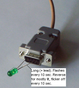
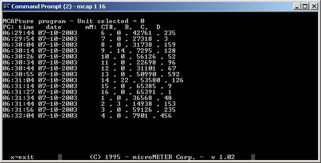
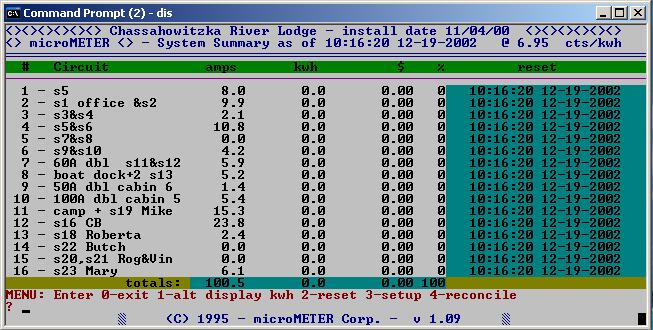
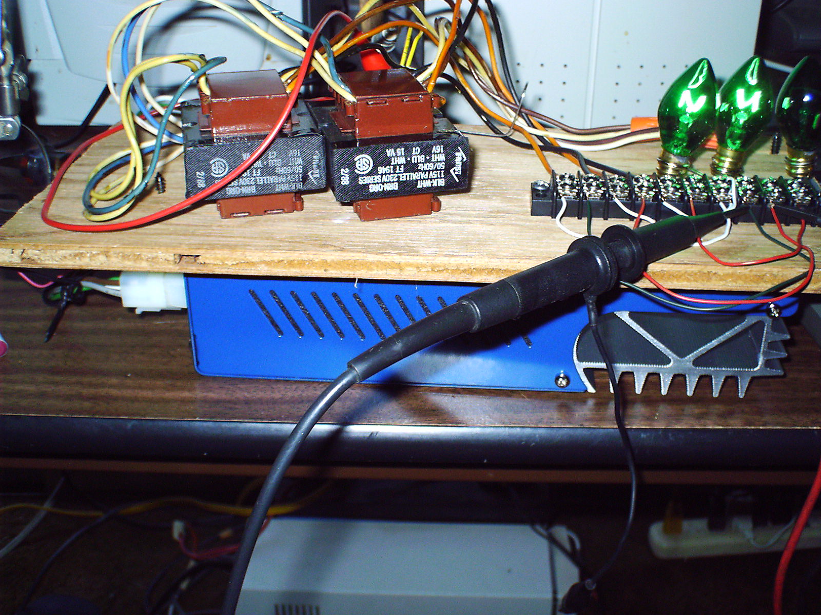
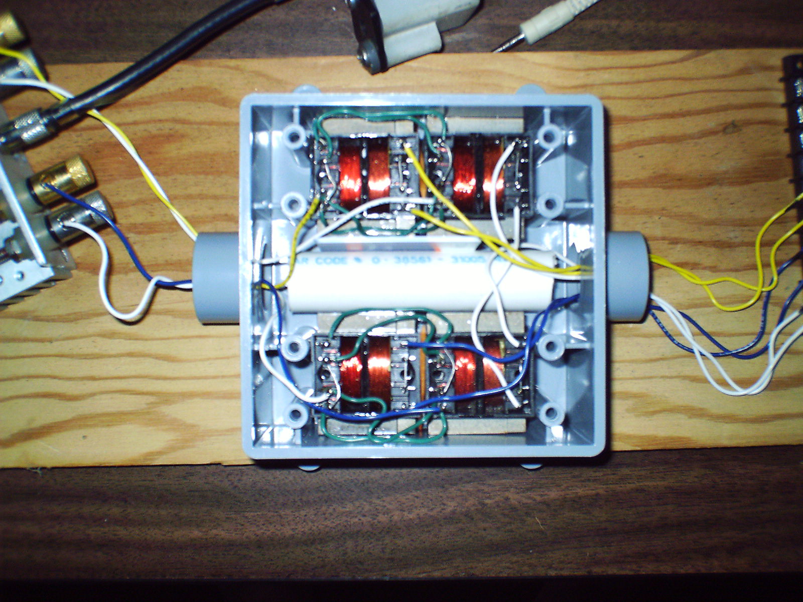